
William Orvis, LUNAR#309
After building the MicroMaxx Rack rocket couple of years ago, I decided to go in the other direction. C engine rack rockets are pretty standard and D engine racks have also been done, so, it seems like it is time for an E-engine rack rocket. E12-0 engines had just come available and are just the just the ticket for a rack.
Figure 1. The Rack Rocket Fleet: MicroMaxx, 18mm (C-motor), and Maxx (E-motor).
Rack rockets are sort of four stage rockets but without the stages. They do have four engines in a stack, but the engines eject out the back of the rocket instead of being carried away with a stage. Hence, it is a rack of engines or Rack Rocket. Rack Rockets are also built as throw away rockets as they are really small and tend to fly really high, usually never to be seen again.
Figure 2. The Maxx Rack Rocket with Jake helping.
For this rocket, I am using four E12 series engines. In my rack that used C series engines, the weight of the engines prevented the rocket from getting up to speed quickly enough to be stable. I had two of them go up about 50 feet turn sideways, and fly off over the hill tops for about a half mile. In an E series rack, the weight of the engines is going to be considerably larger. An E12 engine has twice the thrust of a C6, but it has about 4 times the weight. To alleviate this problem, I added two outrigger engines at the bottom of the rocket to give it an extra kick at launch.
Figure 3. Outrigger engines on the bottom of the rocket. Note the damage to the lower support ring caused by the engines.
The general design is a nosecone, a body tube, three rails (the rack) to contain the engines, a ring to constrain the rails and some fins. Use a streamer instead of a parachute, as this rocket will reach nearly 3000 feet and you can only fit a 12-inch parachute in the engine tube. At 3000 feet, you will be lucky to see a 12-inch parachute while a streamer of some flashy material at least gives you a chance. A streamer will also bring it down somewhere close to the launch pad while a parachute could carry it far, far away.
Parts
This rocket consists of a 12-inch piece of 24mm engine tube and a nosecone from my junk box that fit. Engine tube is a little heavy for a rocket body, but this is Ok for a rack rocket because the weight of all the engines you are going to install at the back needs more weight at the front to make it stable. The thickness of this engine tube also sets the spacing between the engines and the rails. The tube I used has 1/16-inch thick sidewalls. You will need a second piece of engine tube to use as a jig to center the rails during construction.
The rails are three 12-inch pieces of 1/4-inch hardwood dowel. These were from the garden section of the hardware store and were sold as planter sticks for holding up tomatoes, peppers and other plants while they get established. The rails do not have to be round, but could be square. It just depends on what you have available.
The lower support ring is a one and a half inch long piece of BT-60 body tubing You need a heavy duty a ring here as this ring takes a lot of abuse from the burning engines. To thicken it up, I took a second piece of BT-60 tubing, slit it down one side, spread glue around the outside of the first piece and snapped the second one around it making it double thickness.
The Fins are 1/8 balsa.
I added two additional engine holders for two C sized engines to give it a little extra kick at the start to get things moving. Those engine holders are 3 inch pieces of BT-20 tubing with nose cones. Again, the nosecones were whatever I had in my junk box that fit.
To finish it off, you need two quarter inch launch lugs about one inch long, 18 inches of heavy Kevlar cord for a shock cord, an engine block, and 6 feet of shiny silver ribbon about ¾ wide for a streamer. You also need a roll of adhesive backed aluminum tape. This is the tape is actually used for heating ducts (not duct tape), but here we use it to protect the back end of the rocket from the fire from the engine. The tape I found is a peal and stick aluminum foil tape and comes in a 2 1/2 inch wide roll.
Construction
Attach the engine block. Glue the engine block in the engine tube 3 1/4 inches from the end of the tube. This allows an E series engine to hang 1/2 inch out of the end of the engine tube.
Make a centering Jig. Insert an engine (used or new) half way into a second piece of engine tube and slide that into the back of the engine tube you just glued the engine block into. Make sure this tube is straight with the first tube and tight, as it is the alignment jig for the rails and the rear ring.
Figure 4. Engine tube with the alignment jig attached.
Attach the 3 rails. The three rails overlap the bottom of the engine tube by 1/2 inch. This allows for the last engine to project just beyond the bottom of the rocket. As you can see in the picture, I had to add some 2-inch pieces of dowel as braces as the 1/2-inch overlap was not strong enough. 13 inch pieces of dowel would alleviate that problem but I only had a package of 12 inch dowels. Remember, we are assuming this rocket is going to get lost so it was not worth another trip to the hardware store. Besides, the 12-inch dowels were free as I found them in my wife’s garden box.
Figure 5. Attachment of the rails. Note the additional bracing added to strengthen the attachment.
Glue the rails to the end of the engine tube and wrap a couple of rubber bands around them to hold them tight and equally centered around the tube. This is where the second body tube used as an alignment jig gets really handy. Without it, it is really difficult to get the rails centered and straight. If they are not straight, the engines will not slide easily down the rails and eject out the back of the rocket.
Attach the lower support ring. Slide the lower support ring over the outside of the rails and glue it in place. It should hold the rails snugly against the centering jig. If it is tight, you can trim the outside of the rails (not the inside) until the ring fits.
When the glue is dry, cut the rubber bands to remove them.
Attach the 3 fins. The 3 fins are made from 1/8 balsa and can be whatever shape makes you happy. I made trapezoidal fins with a 3-inch root and 3 inches tall. There is no need to sand the fins as they are going to be covered in aluminum tape. Notch the root of the fin a little so it fits snugly against the support ring and the dowels. Glue the three fins in place.
Attach the C engine mounts. Make two engine mounts for 18mm series engines by gluing a nose cone in a piece of BT-20 tubing. There are no engine blocks in these tubes. The engines butt up against the back of the nosecone. Adjust the length of the tubing so an 18mm engine hangs out about 1/4 inch. Glue two of these assemblies to the joint between a fin and the lower centering ring. Place them so they are roughly on opposite sides of the rocket (See figure 3).
Test that an engine can slide between the rails. Slide an engine between the rails and make sure it can easily slide down and out the back of the rocket. Make sure it cannot pop out between the rails. Things will be a little bit tighter when you add the aluminum tape so make sure there is room for it. If things are too tight, sand the inside of the rails to loosen things up. If things are too loose, you can probably tighten them up when you add the aluminum tape.
Attach the launch lugs. Between the third fin and the support ring (the fin that does not have an outrigger engine attached to it), glue a quarter inch launch lug. The second launch lug goes at the bottom of the engine tube. You will need to make a little platform from balsa scrap about 1/8 inch thick under the front launch lug to make it align with the rear one.
Attach the shock cord to the engine tube. Cut 2 slits in the engine tube about 5 inches from the front and about 3/8 inches apart, perpendicular to the long axis of the tube. Bend the tube between the slits down into the tube far enough so you can slide the shock cord through the holes. Tie a knot in one end of the shock cord. Press the end with the knot through the rear hole and the rest of the shock cord through the front hole, down through the inside of the tube and out the front of the rocket. Place glue on the two slits and the shock cord and using a piece of dowel, reach down inside the engine tube and press the slit cardboard back up as far as you can, locking the shock cord in place. Spread more glue over the slits to lock it in place. Tie the other end of the shock cord to the nosecone.
Figure 6. Shock cord attachment.
Attach the streamer to the shock cord. The streamer has to be cut in half because even rolling it up tightly, the whole thing will not fit in the body tube. Cut it into two 3-foot lengths. Tie two loops in the shock cord. Slide one end of a streamer through a loop, fold it over and glue it with CA glue. Do the same with the other streamer. When the glue is dry, roll up the streamer as tightly as you can and slide it into the engine tube. Do the same thing with the second streamer and slide on the nosecone.
Figure 7. Streamer attachment.
Add the aluminum tape. The rails, fins and lower support ring are bathed by the fire of the burning engines so they have to be protected. Cut the aluminum tape into strips as necessary and cover the rails, the fins, and the lower support ring. Put a double layer on the lower support ring, as it seems to take the most damage. Don’t skip this step. Without the aluminum tape, the third engine will burn off the whole back end of the rocket, including the fins. Rockets fly really funny without fins.
Test that engines can slide out. Make sure that engines can easily slide between the rails and out the back of the rocket but not pop out between the rails. Adjust things as necessary until an engine will slide out easily. You may need to remove the tape and sand the inside of the rails if things are too tight or add additional tape if things are too lose.
Flying the rack.
Remove the nosecone and streamer and put three small balls of recovery wadding in the engine tube. Reroll the streamer and place it in the engine tube and reattach the nose cone.
Take an E12-7 engine and tape an E12-0 engine to it using scotch tape. Make sure the top of the E12-0 engine (the end without the nozzle) is taped to the nozzle end of the E12-7 engine. Take another E12-0 engine and tape it to the nozzle end of the first E12-0 engine. Take a third E12-0 engine and again tape it to the nozzle end of the second E12-0 engine. When you are done, you have four engines taped together in a line with the top end of one engine taped to the nozzle end of the next engine. Slide this assembly into the rocket with the E12-7 engine first, sliding up between the rails and into the engine tube. This should fit tight. If it is lose, slide the engines out, add some masking tape to the E12-7 engine and slide it in again. Do this until the E12-7 engine fits tightly into the engine tube and will not pop out when the ejection charge fires.
Insert two C6-0 engines into the two engine pods at the back of the rocket.
Install three igniters into the three engines at the bottom of the rocket. Wire the igniters together in parallel. I have found that using wirewrap wire and a wirewrap tool makes a very reliable connection between the igniters.
Figure 8. Ready to fly.
Launch the rocket from a pad with a quarter inch launch rod. Get some friends to help spot the rocket after launch. A Rocsym simulation of this configuration goes over 2900 feet, and seeing a rocket this small at that altitude is going to be hard. Luckily, the silver ribbon sparkles in the sunlight and can usually be seen.
I have flown this rocket three times and recovered it each time. It has needed to be rebuilt each time, the first time, the engine burned through the lower support ring and the rails broke off the engine tube. The second time the fire from the engine burned through the lower support ring again. The third flight, everything stayed attached but the lower support ring is badly damaged again.
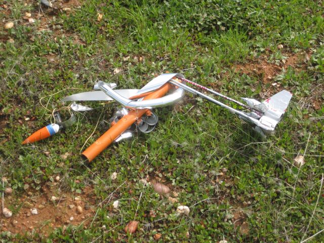
Figure 9. During the second flight the rails burned off.
Maybe it is time to build a bigger rack. I hear Estes has a black powder F15 engine that can be staged. ☺