All About Rocket Engines
All About Rocket Engines
All About Rocket Engines|
Return to contents
Previous Section
Next Section
There are essentially two different types of commercial model rocket engines,
black powder and composite. One new type of engine uses a combination of liquid
nitro (racing car stuff) and cellulose as the rocket fuel. This combination engine
is being designed to overcome the problems with shipping larger engines containing
flamable fuel.
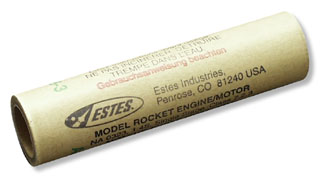
The most commonly used small model rocket engines are the black powder
engines such as the one shown below. These are the "traditional" model
rocket engines that have been in production since the 50's.
Black powder model rocket engines are made of a paper
tube with a clay nozzle, a solid pellet of black powder propellant,
a smoke/delay charge, and an ejection
charge as shown in this figure.
Booster engines are similar but lack the Smoke/Delay
and ejection charge.
A model rocket engine is ignited by inserting an
igniter in the clay nozzle putting it in contact with the propellant. At
launch, an electric current is driven through the igniter, causing
it so explode, igniting the propellant.
When the engine is ignited, the propellant burns,
ejecting high-pressure gas out of the nozzle and producing thrust
in the opposite direction.
When the propellant is completely consumed, the smoke/timer
charge burns producing a smoke trail. The timer charge performs
two tasks. First, it provides a smoke trail to help you follow
the flight. Second, it lets the rocket coast to its maximum height
before activating the ejection charge.
When the smoke/timer charge is exhausted, the ejection
charge fires, which pressurizes the rocket body and deploys a
parachute or other recovery device.
Single use composite model rocket engines are made from a high temperature plastic
and the fuel is a pellet of a rubber like material similar to that used in
the Space Shuttle booster engines. The fuel in a composite engine is about three times
as powerful as black powder so engines of equivalent power
can be made in a smaller size.
The internals of the composite engines are much the same as the black powder motors
except that the nozzle and body of the engine is molded from a high-temperature
plastic. The engine body contains the fuel, a smoke/timer charge,
and the ejection charge.
Reloadable composite engines are essentially the same as single use composite engines. They use the same fuel,
timing charge and ejection charge but are assembled in an aluminum case.
The case is reusable. After it has been cleaned, it can be reassembled with a new nozzle, fuel,
delay charge and ejection charge, and used again. The chief benefit of reloadable engines is that they are less expensive than single use
composite engines. And, it is fun to build your own engine before a launch. High power model rocket engines are only available as reloadable engines Return to contents. Understanding Model Rocket Motor CodesModel rocket engines are marked with a three character code that specifies the approximate operating characteristics of the motor. The code consists of a letter and two numbers such as D12-5.
The letter is the total impulse, the first number is the average thrust in Newtons, and the second number is the time delay in seconds to the initiation of the recovery system. Hence, the motor in the figure is a class D total impulse engine with an average thrust of 12 Newtons and a time delay of 5 seconds. Return to contents. Total ImpulseThe letter indicates the total impulse class of the engine, which is effectively the amount of fuel in the engine. The total impulse is the total momentum change that an engine can impart to a rocket. Total impulse is measured in Newton-seconds (pound-seconds). The standard impulse class for each letter is shown in the following table.
Most commercial model rocket engines are built to operate at the top impulse level of their class, but this is not a requirement. An engine may actually operate anywhere in its impulse class range.
Return to contents. Average ThrustThe number following the letter indicates the average thrust of the engine in Newtons (pounds). Because the amount of fuel in an engine is fixed by the class letter, an engine with higher average thrust burns up its fuel more quickly than one with lower average thrust. As a rule of thumb, the duration of a burn is roughly equal to the total impulse divided by the average thrust. Here is a typical thrust profile for an engine with an average thrust of about 6 Newtons.
A typical engine starts with an initial high thrust for a fraction of a second, which is useful for getting things moving. It then settles down and burns the remainder of the propellant at a relatively constant rate. Return to contents. Time DelayThe last number on an engine is the time delay, in seconds, to activation of the recovery system. The propellant in a model rocket typically burns up in about 1 second. At that point, the rocket is still moving upward at a high rate of speed. If you were to activate the parachute at this point it would likely be shreaded. What you want to do is to let the rocket coast up to its highest point and then activate the parachute. The time delay charge is the mechanism for delaying activation of the recovery system until the rocket reaches its highest point. The time delay charge also emits smoke to make the rocket easier to track. When the smoke charge burns out, it ignites an ejection charge that activates the recovery system.
Time delays are typically 3 to 8 seconds, with short time delays needed for larger heavier rockets and longer delays needed for lighter ones. Do not use too long of a time delay as it may allow your rocket to impact the ground before activating the recovery system. Such impacts endanger the spectators and are really hard on your rockets. Rocket motors marked with a time delay of 0 seconds are booster engines. A booster engine is used in the lower stages of a multi-stage rocket and has no time delay and no ejection charge. When the fuel finishes burning there is a flash of flame out the back of the engine that is used to light the next engine in a multi-staged rocket. Only the top stage in a multi-staged rocket needs an engine with a time delay and an ejection charge. Rocket motors marked with a P instead of a number for the delay charge are "plugged" engines. A plugged engine is similar to a booster but the forward end is plugged so no fire comes out the front when the fuel finishes burning. These are used in some gliders and in situations where you do not want a blast out the front. Return to contents. Engine Sizes
Model rocket engines come in several standard sizes
so that whenever possible, engines of different total impulse
and from different manufacturers may be used in the same rocket.
The more common engine sizes are in blue.
Return to contents. NAR Certified EnginesIn California, only engines certified by the National Association of Rocketry (NAR) can be flown. They must also be certified by the State of California but NAR certification is needed first. The current list of certified engines is available on the NAR website.Return to contents. Installing An EngineHow you install a rocket engine in a rocket depends on the particular rocket. The simplest installation has a wrap of tape placed around the nozzle end of the engine and then the engine is forced into the engine mount. The tape provides a tight fit so the engine won't pop out when the ejection charge fires. A problem with this type of engine mount is that the engines can be difficult to remove after a flight. It is useful to have a three foot piece of hardwood dowel that can be slid down the rocket tube from the front to push the engine out the back. Another simple installation, is to tape the engine in place. This installation only works if a sufficient amount of the engine mount is accessible so that you can tape to both it and the engine. This method does have the advantage that it is easier to remove an engine after a flight. Many models have a metal clip that holds the engine in. The clip is pushed to the side, the engine is inserted into its mount and the clip snaps back when the engine is fully inserted. This type of mount also allows easy removal of an engine after a flight. For some models you do not want the engine to stay with the model but you want it to be ejected when the ejection charge fires. Models of this type include those that employ tumble recovery and those that change to a glider. Return to contents. Using Igniters
The simplest igniter consists of a short wire with
a high resistivity section in the center that is coated with some
explosive. The igniter is inserted in the back of an engine and
held in place with a plastic plug or with a small ball of recovery
wadding held in with tape.
To launch the rocket, it is placed on the launch wire and the launch controller is attached to the igniter wires with two alligator clips. To fire the rocket, a current is pushed through the wire causing it to heat up and ignite the explosive. The explosive then ignites the engine. Note how the igniter wires are bent into an arc so that the alligator clips can get a better grip on it.
A different type of igniter is the copperhead. This igniter consists of a strip of plastic with copper on both sides. A small ball of conductive explosive is placed on one end. It is also inserted into an engine, but a special clip is used to attach it to the launch controller. The clip has two wires attached to the two sides of the clip. When the clip is placed on the end of the igniter, the two wires attach to the two copper films. The rocket is fired in the same way, with a current driven through the copper strips that ignites the explosive. We have had a lot of misfires using copperhead igniters. The problem is usually a short across the plastic strip caused by bending or twisting the igniter such that the two copper strips come into contact.
Igniterman style igniters are made by stripping the insulation off of a quarter inch of two wires and then twisting all but the end of the wires so that the stripped ends are close (about the thickness of a thick sheet of paper) but not touching. This end is then dipped in a flammable conductor that creates a thin film between the two wires. Running a current through the wires and the film causes the film to ignite. After the film dries, the igniter is dipped in a pyrogen mixture. This mixture causes a small explosion that ignites the rocket fuel. Return to contents. Two-Stage RocketsIn most two state rockets, a booster engine is taped to an upper stage engine. The booster engine has no smoke/delay charge or ejection charge so when the propellant is consumed, the burn blows out the back of the engine, which ignites the second engine and burns through the tape, separating the booster from the upper stage. Note that taping only works for black powder motors.
More complicated rockets and rockets that have a composite engine as the upper stage use a timer and an electrical igniter to fire the upper stage. Return to contents Previous Section Next Section |
All content is the responsibility of LUNAR.
If you have comments or suggestions regarding these web pages,
please contact the 
Copyright © 1992 - 2026 LUNAR