Helping Out
Helping Out
Helping Out|
Return to contents Previous Section Next Section The LUNAR model rocketry club is not just a service for rocketeers, it is an all-volunteer organization where everyone is expected to help out. Setting up, tearing down, and taking a turn in one of the following positions is a LUNAR membership requirement.
None of these jobs are very difficult, many can be done by our younger members,
and when we all do our fair share
they are not a burden. In fact, the Go to the Front
of the Line Return to contents. Setting Up For A Launch
People wanting to help with setup should try to arrive
at the field around 8:00 a.m. as we usually try to start flying by 9:00.
Go to the trailer where the equipment is being
unloaded and say "I want to help",
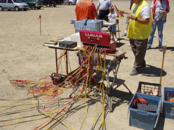
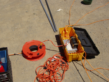
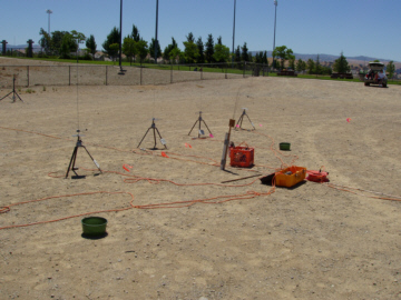
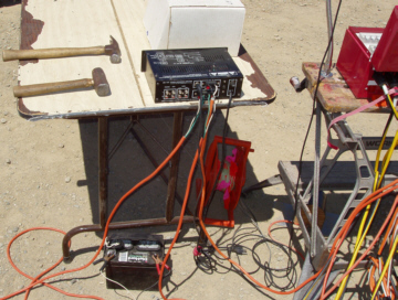
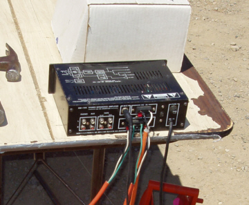
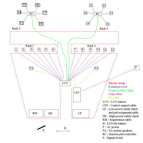
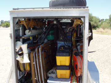
we'll put you to work. Step one is to start unloading the trailer, especially the center section as it needs to be cleared out to get to the extension cords hanging on the walls. The second step is to set up the LCO Station, which is a collapsible worktable stored at the back of the trailer and the Launch Controller (a red, metal toolbox). The Launch Controller clamps on top of the worktable. Everything else is setup relative to the LCO Station. See the diagram below for the setup. As soon as the LCO Station is in place the rest of the setup can continue.
Bring out the extension cords and sort them by number. Numbers 1 through 6 fan out in front of and to the left of the LCO Station out to Rack 1 (pads 1 through 6). Tie (a half hitch) cord number 1 to the cross bar on the front of the worktable and plug it into socket number 1 on the Launch Controller. Unroll it out in front of the LCO Station about 30 degrees to the left of straight ahead. Unroll it almost to the end, leaving a few feet for adjusting the final location. Do the same with cord 2, going from socket 2 on the Launch Controller, roll it out just to the right of cord number 1. End with it about six feet (two big steps) to the right of the end of cord number 1. Continue with cords 3 through 6.
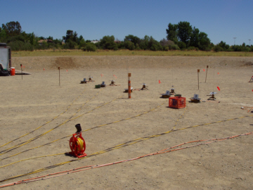
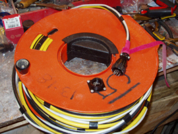
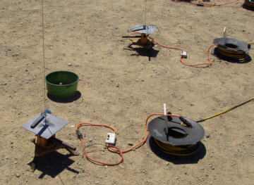
WARNING: Be really careful here to be sure that cord 1 goes in socket 1 and out to pad 1, and so forth for the other cords and pads. Failure to do so could get someone hurt. Extension cords 7 through 12 fan out in front of and to the right of the LCO Station, out to Rack 2 (pads 7 through 12) in exactly the same manner as cords 1 through 6. Rack 3 (pads 13 through 18) are the mid-power pads and are directly behind rack 1, but 100 feet farther away. There are two reels marked 13 through 18 that contain a yellow and a gray cable taped together with a single male connector on the end and a female connector on the side of the reel.
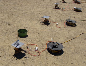
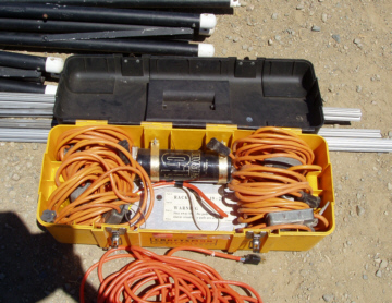
Tie one of these cables around the cross bar on the LCO station and plug it into the matching connector marked 13 through 18 on the back of the launch controller. Be careful when you plug it in. When you have it right, it goes in easy and you can twist the lock ring to hold it. If it does not seem to be going in easy, unplug it and see what is wrong. Make sure there is no dirt or sand in the connector. Unroll this cable down the center of the field between the two banks of low power pads. When the reel is empty, set it down and plug the second reel into the connector on the side of the first. Veer to the left so you end up with the reel near where you want the center of the bank 3 pads. Carry the Remote Launch Controller (a yellow and black plastic toolbox) out to the end of the cable. Open the tool box and remove all the cables. Plug the matching power and control cable into the matching connector on the side of the second reel. Unwind the six cables and arrange them in a semi-circle around the controller. Be sure to do them in order, going from number 13 on the left around behind the controller and ending with number 18 on the right.
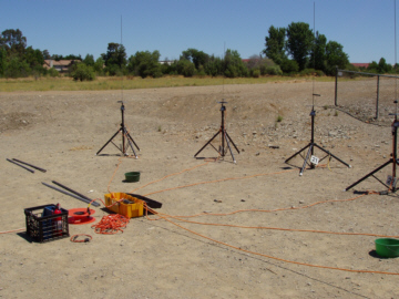
Rack 4 (pads 19 through 24) are the high power pads. They are setup exactly the same way as rack 3 except they are behind rack 2. We also have three reels of cable for the high-power pads though we only use the third reel when we are flying at Snow Ranch. Using the third reel places the high-power pads 300 feet from the LCO table. There are two six foot extension cords in the remote launch controller for rack 4. Place these cords on pads 19 and 24 so those pads can be spread out more to make them more visible.
Next come the pads themselves. Pads 1 through 12 are the small pads which are primarily for low power rockets. Put one pad within reach of the end of each extension cord. Put about six feet (two big steps) between each pad and about 15 feet between pads 6 and 7 (the last pad of Rack 1 and the first pad of Rack 2).
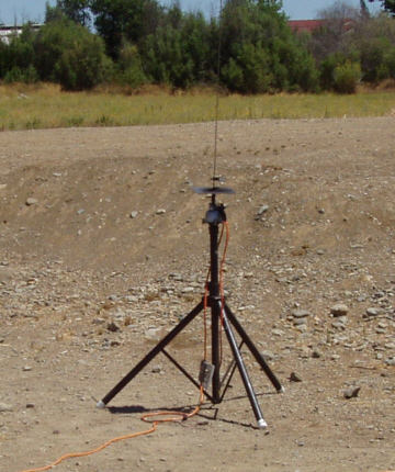
The medium sized pads are rack 3 and are setup in much the same way as racks 1 and 2. Pads 19 through 24 are the black collapsible tripods. Extend the tripod and place one near the end of each cable. Don't tighten the tripod clamps too much. They only need to be snug. There is a loop on the continuity tester at the end of each cable. Hang that loop on the tripod clamp knob. If the loop is missing tie a half hitch in the cable and loop it over the knob.
There is a milk crate for each of the 4 racks of pads. They are marked rack 1, rack2, rack3, and rack4. Put this crate near the center of each rack. Each crate contains a fire extinguisher, a blue box with the blast deflectors and pad number signs, assorted igniter clips (both alligator and Copperhead) plus a blue can with some large nails and cleaning supplies (Scotch Brite pads and a small wire brush). Let a club officer know if any of this equipment is missing. Use the nails to fasten the three legs of each pad down to the ground. Put a blast deflector on each pad and stick a pad number in the ground in front of the pad. Put a standoff clamp on each pad. For racks 1 and 2, plug the numbered continuity testers into the extension cord. For all pads, plug an alligator style igniter clip into the continuity testers. Put the green plastic trash tubs within reach of the pads. The extra igniter clips are draped on the spare launch rod tube (described next) to keep them off the ground. The launch rods are in two large white tubes. Take the long tube out between Racks 3 and 4 and put the short tube between Racks 1 and 2. Each rack of pads gets a launch rod holder. These are smaller tubes about 2 feet long and 3 inches in diameter that keep the launch rods off of the ground so they don't get stepped on. The launch rod holders have small loops on the sides that go over one of the metal stakes we use to hold up our safety barrier. Put one near the center of each rack of pads. Put 1/8 inch rods in pads 1 through 12, through the hole in the blast deflector and clamp the standoff to the launch rod. Get a few of the 3/16 and 1/4 inch rods from the larger tube and put them in the launch rod holders at Racks 1 and 2. Spread the larger rods between the launch rod holders for the high-power Racks (3 and 4). You don't need to put launch rods on the high power pads as the high power users will pick the rods they need.
WARNING: don't leave any of the launch rods laying on the ground. Someone will step on them and bend them all out of shape. Stainless steel rods are very difficult to get straight again after they have been bent. Also, you will piss-off the equipment manager and you really don't want to do that. You might get invited to spend a weekend cleaning and straightening launch rods. While the pads are being setup, The LCO Station gets setup with the control support table, battery (or power supply), amplifier, microphone, and foot switch. Plug the foot switch into the back of the launch controller and place it on the ground. Plug the power cable into the back of the launch controller. The power cable has two trimmed wires for attachment to the power input connectors on the back of the amplifier. Place the alligator clips near the battery but do not connect them until everything is setup. Plug the microphone into the amplifier and place it in the holder on the LCO table.
In the same area are the high-power and low-power safety check tables. An electronic scale and engine performance charts go on the high-power safety check table. A small box of repair materials (glue tape, etc.) goes on the low-power safety check table. The white board for job signups goes in front of the safety check tables. The club banner also goes in front of the safety check tables. Registration is done on a table next to the high power safety check table. The table needs to be setup with the registration box, sign-in sheets, transaction log and member roster on clipboards, pens, and cash box.
The speakers for the PA system need to be setup and connected to the amplifier. The speakers are on poles that are held up with three ropes. Use two of the unmarked extension cord reels to connect from the speaker to the amilifier. An adapter goes on the end of the extension cord to allow it to be connected to the speaker connectors on the back of the amplifier. The speaker for the Heads-up siren needs to be plugged into the Launch Controller and rolled out in front of the LCO Station. The barrier string can be put up as soon as all the pad cords and pads are in place. Put metal stakes (from the wagon) in the ground to make the shape shown in the setup figure. There is a stake pounder made of pipe in the trailer. Put a wooden block on each metal pin. Start and finish unrolling the barrier string at the LCO Station, rotate the support blocks so that the barrier is always to the inside of the stake and pull it fairly tight as you install it. If it looks like enough people are doing setups, any additional workers can help in the equipment staging area by cleaning the launch rods with the Scotch-Brite pads and cleaning the launch clips with the small wire brushes. Return to contents. Tearing Down After A LaunchThis starts with picking up all the trash from around the pads and placing it in the trash buckets. Then it's just a matter of consolidating all the hardware carrying it over to the pickup area next to the trailer. The pad numbers and blast deflectors go in the blue boxes in their respective slots. The nails and standoffs go in the blue cans. The blue box and can go in the milk crate with the fire extinguisher and the igniter clips are stuffed on top.
At the mid- and high-power pads, unplug the remote launch controllers from the wire reels, wind up all the wires that go to the pads and stow them in the remote launch controllers. The two, short extension cords at the high-power pads are also stowed in the remote launch controller boxes.
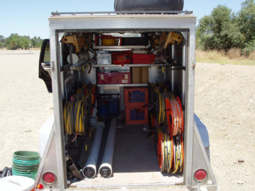
When pulling the pads off the ground, pull on the legs next to the spike to avoid breaking the legs off the pads or use the claw hammer to pry them out. After removal don't leave any low profile objects (steel stakes, launch rods, igniter clips, blast deflectors) sitting off by themselves in the grass as they may be overlooked and left behind when we leave. Filling the trailer is an art. If you do it wrong, it won't fit. Things have to be loaded in order for it all to get in.
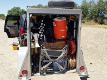
As shown above, the launch controller, scales, camping lights, and other small items go in the back of the trailer. On the bottom back are three of the milk crates. The 12 low power pads go on the 12 pegs along the top of each side. The cable reels go on the lower rows of hooks, with the winding knobs towards the wall for the inner reels and towards the inside for the outer reels. The large high-power pad numbers are behind the reels on the left side. The two launch rod tubes (white) go on the floor with the longer one going under the wooden stool at the back of the trailer. Put the "Open This End" end of the tubes to the back so the equipment manager can get launch rods out without having to unload the trailer. The launch rails go either in the launch rod tubes or go on the floor between them. On the rest of the hangers on the sides go the pipes for the banner, speakers, launch rod tubes and any other long, skinny objects. The pipe hammer for pounding the stakes in the ground goes on the bottom left under the reels. The ball hitch is on the left bottom at the back.
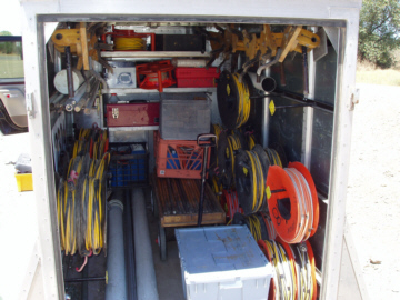
The next step is to back the wagon contiaining the steel stakes into the trailer all the way to the back on the right side. Pile two milk crates on top of it. Put the large, blue box behind the wagon.
Put the two small blue boxes on the wagon. Put another milk crate on top of the other crates and the boxes. Put the two, yellow and black remote launch controller boxes on top of the large blue box and the back of the wagon. Push them up against the small blue boxes.
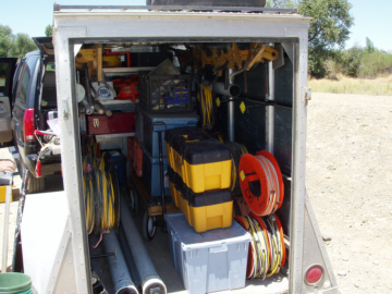
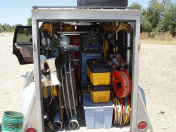
The four tables and the sign-up board go on top of the launch rod tubes and slide as far back as possible.
The mid power pads slide in a track at the top-center of the trailer and slide all the way to the back.
The high power pads slide in on the top-left side. The large black bag of dog barf (fireproof ceiling insulation to use for recovery wadding) goes in under the mid-power pads. The drinking cups go in the orange water container which goes on top of the remote launch controllers. The battery goes on the bottom at the back. The last thing to go in is the folded up launch controller table. Before closing things up, make sure that the battery is at the back of the trailer so it can be removed and charged. The trailer hitch should also be on the bottom left at the back (unless it is being used to tow the trailer). Close and lock the back. The trailer is parked in the fenced in area by the back gate of the rodeo grounds. Back the trailer in and sit it on the trailer stand. Open the trailer and put the trailer hitch at the back at the bottom-left side. Close and lock the trailer. Put wheel covers on the two wheels. Close and lock the gate. Return to contents. Extra Benefits For Helping
There are special benefits for those that help out
at a launch. For those of you who do setup or tear down
you receive four free low-power flight cards or one high-power flight card.
However, the
best benefit are for those who do the RSO, LCO, LP-SCO, HP-SCO, PAD, LPS or
RM jobs. In addition to the flight cards, they get a
Go to the Front of the Line
Return to contents Previous Section Next Section |
All content is the responsibility of LUNAR.
If you have comments or suggestions regarding these web pages,
please contact the 
Copyright © 1992 - 2026 LUNAR
 you get for doing these jobs
make it well worth while, especially on a busy day.
Everyone who does a field job gets a dollar’s worth of flight cards as payment.
Those who help set up and
tear down get the flight cards, but not the Gold Card, since those particular jobs
don’t take away from flying time. Sign up for jobs on the white board
in front of the Safety Check area.
you get for doing these jobs
make it well worth while, especially on a busy day.
Everyone who does a field job gets a dollar’s worth of flight cards as payment.
Those who help set up and
tear down get the flight cards, but not the Gold Card, since those particular jobs
don’t take away from flying time. Sign up for jobs on the white board
in front of the Safety Check area.