Return to contents.
Lights and Flashers for Night Launches
Revised 4/19/1998
by William J. Orvis, LUNAR# 309
Participating in a night launch is great fun but you must light your rocket to be safe. In this article I will show you some things to consider while designing and building your rocket to make it safe and look cool at the same time.
- Flashing LEDs
- Simple Flasher - Using a 555 Clock
- Building the Circuit
- Alternating Flashers
- LED Chaser
- Modified Toys
- WARNING; They Bite !!!!!
- A Basic Flasher Circuit
- Modifying Disposable Cameras
- Triggering With Two NE-2s
- Triggering With An SCR
- Making It Flash Faster
- Making It Fit In A Rocket
- Using the ALL FSH-1 Flasher
- Miniature Toggle Switches
- Closed Circuit Phone Jacks
- Finger Strips
- Wire Short Between Two Batteries
- PC Board Connectors And Jumpers
- 9V Battery Snap
Participating at night launches of model rockets has turned out to be the most fun I have had in ages. Not only do I get to make a rocket that flies and looks cool, I get to cover it with lights and flashers so that it can be seen in the dark. Now I could just stick a AAA battery and a flashlight bulb in the nose cone but part of the fun is having a rocket that looks good (or outrageous) in the dark.
Besides looking cool and letting you see the rocket on the way up, lights have an important function at night launches; they let you see the rocket on the way down. That way you can tell if it's under the control of the recovery system or if it's coming down ballistically. It's really spooky when a rocket comes out of the dark and prangs into the ground next to you. Considering the large audience we have at night launches it is even more important to have the rockets well lighted so no one gets hurt.
That said, you might think that lights are limited to the larger rockets; not true. Any rocket can be lighted and still fly. I have put four LEDs and two batteries in an Estes Mosquito and had a great flight. In fact, it was the first mosquito launch where I actually saw the rocket throughout the whole flight. Anyway, if I can put lights on a mosquito, you can put lights on anything that flies.
Return to top.
I. Maximum Launch Weight
A difficulty with lighted rockets is that there is a lot of weight in batteries and circuits that adds to the total weight of the rocket. Most of the problem flights at night launches result from under powered rockets. So, the first thing to consider is the maximum launch weight for the rocket. The launch weight is the total weight of the rocket as it sits on the pad including the engine. Try to keep the total weight of the rocket below the maximum launch weight listed for the engine you are using or your rocket may not fly well. Though it is a great crowd pleaser to have your rocket splat into the ground and then eject the chute.
Table 1 lists the maximum launch weight listed by the manufacturer for a few of the more common short delay engines. The maximum launch weight is determined by the initial and average thrust, the total impulse, and the duration of the delay charge. Therefore, if you go to a longer delay or to a lower thrust engine, you must lower the maximum launch weight. A complete table is available from each manufacture for their engines. If you exceed these weights by any significant amount, your rocket will not gain sufficient velocity at launch to be stable. Any small gust of wind could flip it and send it towards a multitude of soft pink ground targets or it could simply arc over into the ground. While this may be a satisfying way to get back at a crowd that laughed at your rocket, it might get you kicked off the field. An under powered rocket also may not go high enough for the recovery system to deploy, which has the same result.
The weights on this table are not absolute limits. That is, your rocket is not definitely going to splat if you exceed these weights. There is more to the equation than weight, but you must be extremely careful if you exceed these weights. Stability is also controlled by balance and aerodynamics. An aerodynamic rocket (a long thin rocket with large fins only at the rear) with the weight well forward of the center of pressure can exceed these limits and still be stable. I have flown an Estes Big Bertha on a C6-3 with a payload section containing a flasher, a light chaser circuit, 2 AAA batteries, a 9V battery, and 10 LEDs. The total weight was almost eight ounces, four ounces over the weight limit for the C6-3 engine but the rocket was aerodynamic, it had a lot of weight in the nose (all the lights and batteries), and there was no wind. We called a "Heads Up" launch just in case, but it was a perfect flight (cool looking too with all the lights and flashers going at the same time.)
If at all possible, try to not exceed the weight limits. You are much more likely to have a successful flight if you don't. If your rocket looks like it is going to be under powered, consider adding a couple of boosters to it. Two short pieces of tubing with nose cones glued to opposite sides of your rocket makes an easy pair of boosters. You may need to add only a couple of mini engines to get your rocket moving fast enough to make it stable. For example, two A10-0T engines increase the maximum launch weight by 10 oz (282 gm, 5 oz per engine). If you add boosters, don't forget to add the weight of the boosters to the launch weight of the rocket. For the Big Bertha mentioned above adding two mini engines increases the maximum launch weight to 14 oz (4 + 2 * 5) while only raising the rocket's launch weight to 8.5 oz (8 + 2 * 0.25) which is well within the safe zone.
Table 1, Rocket Maximum Launch Weight Limits for Some Short Delay Engines
(from manufacturers catalogs)
oz. gm. | ||
| 1/2A3-2T | 2 | 57 |
| 1/2A6-2 | 2.5 | 71 |
| A3-4T | 2 | 57 |
| A8-3 | 4 | 113 |
| A10-3T | 5 | 142 |
| B4-2 | 4 | 113 |
| B6-2 | 4.5 | 127 |
| B8-5 | 5 | 141 |
| C5-3 | 8 | 226 |
| C6-3 | 4 | 113 |
| D12-3 | 14 | 396 |
| D13-4 | 16 | 454 |
| D24-4 | 16 | 454 |
| E15-4 | 14 | 396 |
| F12-3 | 18 | 511 |
| F24-4 | 16 | 454 |
| F39-6 | 18 | 511 |
| G33-5 | 22 | 624 |
Return to top.
II. Simple Lights
If you just want a simple light to make your rocket visible, you don't need to create an elaborate lighting system. Here are some simple lights that you can put together with parts you can find at Radio Shack or the hardware store.
Battery and a Bulb
The simplest rocket light is a single AAA battery, a 1.5 V light bulb, and a socket. Solder a wire to each end of an AAA battery being careful to not let the battery get too hot. Solder the two wires to the socket. Insert the bulb to turn the light on. This assembly fits in a BT-20 (0.71 in / 18 mm) payload section. This light works well, is inexpensive, but is not very exciting. The total weight is about 0.4 oz (12 gm). If you put one in an Estes Nova (1.3 oz) plus a C6-5 engine (0.91 oz), the total launch weight is 2.61 oz., which is well under the maximum launch weight of 4 oz of the C6-5 engine.
Incandescent lights are found in many different voltages and currents. A good source for small, low voltage incandescent lights and sockets are miniature Christmas lights. Find an old string of Christmas lights at a garage sale or buy an extra set after Christmas. For about $5.00 you can get 100 lights and sockets. Be sure to get a string with all the lights in series not parallel as the lights in a parallel string operate at 110 volts. In a series string the wire from the plug goes to the first light, a second wire goes from the first light to the second and so forth until the last light in the string connects back to the plug. With the lights in series, the bulbs operate at a voltage of 110 divided by the number of lights. For example, a string of 100 lights in series has bulbs that operate at 1.1 Volts and will work just fine at 1.5 Volts. Cut up the string between each bulb and you have bulbs and sockets with a few inches of wire on each. Miniature Christmas lights are available in different colors and as flashers.
One caveat when using Christmas lights, modern Christmas lights are designed to short when they burn out instead of being open (no connection). In that way, if a bulb fails only the failed bulb turns off while the rest of the string stays on. If you are driving this bulb with some electronics, be sure the electronics can stand having the output shorted. If this bulb is connected directly to a battery, the worst that will happen is that the battery runs down quickly.
Chemical Lights
Another simple way to light your rocket is to use chemical lights. These are available in many different shapes and colors and put out sufficient light to see a rocket in flight. They can only be turned on once, but generally last a whole evening. Some rockets use two chemical lights, one in a nose cone and one attached to the shock cord.
Light Emitting Diodes (LED)
LEDs are just about the best lights for rockets. They are small, bright, come in different colors, and use only a small amount of electricity. A difficulty with LEDs is that they need about 2 V to turn on. Since most batteries only put out 1.5 volts, this means that you must use at least two batteries to make them work. Some of the newer, ultra bright LEDs are as bright as a flashlight bulb. Most electronic supply stores sell LEDs though Radio Shack tends to sell out the week before each Night launch.
The basic LED circuit consists of an LED, batteries, and a resistor. The batteries must be in series and the voltage must total 2 volts or more. The resistor is needed because most LEDs turn on around 2 volts and any more voltage does not make more light, it just wastes power. Choose a resistor to keep the voltage and current down around the optimum level for the LED you are using. The optimum values for the current and voltage are usually listed in the catalog for the store where you obtained your LEDs. Most operate at between 1.6 and 2.2 volts and consume 10 to 20 mA of current. To calculate the correct size for the resistor, subtract the LED voltage from the battery voltage and divide by the diode current to give a resistance. Make the resistor a little smaller to account for the battery running down. For example, a red LED normally runs at 20 ma at 2.2 Volts. If you run it with a 9V battery you have (9-2.2)/20e-3 = 340 ohm. If you have a junction in the circuit, such as a transistor switch or an integrated circuit, subtract another half volt (9-2.2-.5)/20e-3 = 315 ohm. I have used 270 and 330 ohm resistors and they both worked fine.
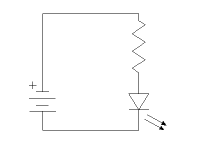
You can drive multiple, identical LEDs from a single battery and resistor though you must adjust the value of the resistor to account for the increased current necessary. For example, to run 2 LEDs in parallel with a 9V battery, the resistor should be (9 - 2.2)/(2 x 20e-3) = 170 ohms.
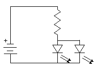
When driving different types of LEDs with a single battery you need to create a resistor network to divide the current between the different LEDs. Different colors of LEDs or normal and high brightness LEDs draw different amounts of current and operate at different voltages. If you don't use a network, the LED that turns on at the lowest voltage sinks all the current making the other LEDs dim. Create a resistor current divider to divide the current and give each LED the voltage and current it requires. To calculate the values of the resisters, treat each LED as if it were the only LED connected to the battery and calculate the resistance in the same way as for a single LED above.
Spotlights
Occasionally you may want a light to illuminate the side of a rocket or a fin to show off some detail of the rocket instead of as a running light. Flashlight bulbs are available with a small lens in the tip that direct the light forward. Some of the high brightness LEDs also have a directed beam instead of a diffuse beam. Either of these lights works as a spotlight. Paint the back of the bulb or LED with aluminum paint if you need to reduce the scattered light. Experiment with the amount of paint you put on the light until you get the beam you want.
Return to top.
III. LED Flashers and Chasers
Here is where we start getting into some interesting circuits to make lights that flash or LED chasers.
Flashing LEDs
The simplest flasher uses flashing LEDs and two batteries. I picked up these special LEDs at All Electronics and they take all the fun out of making random flashers. Simply power them up to have about a 1-second period flasher. They come in red, green, and yellow and cost about $0.75 each but don't need any other electronics but batteries and a switch. Wire them like the simple LED described above.
Simple Flasher - Using a 555 Clock
If you want more control of your flashing, you need to build a simple timing circuit. A 555 integrated circuit is a good simple timer whose period is controlled by an external capacitor and two resistors. You can drive a 555 with anything from 4.5 to 15 volts making a 9 volt battery a convenient choice. With a 20 mA load on the output of the 555 and a 9V supply, there is a 1.5 V drop between the supply voltage and the output when the output is high so use 7.5 V when calculating the resistor to use. With a 9V supply, the 555 itself uses about 5.5 mA so it won't load your battery significantly. The pinout for the 555 in an 8 pin DIP package is shown here.

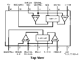
555 Pinout 556 Pinout
If you need two timers on a rocket, use the 556 timer which is two, independent, 555 timers in a single 14 pin DIP package (see above). If you really need to save weight or want to put a timer in a mosquito, you can get 555 and 556 chips in a surface mount package. Be advised, you will need a magnifying glass to see the circuit (the chips are 3/16" x 1/8") and a really steady hand to solder to it.
The basic 555 oscillator circuit is shown below. The 555 operates by alternately charging and discharging the external capacitor (C). Initially, the capacitor charges through resistors R1 and R2 from V+. Pins 2 and 6 detect the upper and lower limits for the capacitor voltage. When the upper limit is reached, pin 7 is grounded, discharging the capacitor through R2. When the lower limit is reached pin 7 is opened, letting the capacitor charge again. You set the flash rate and the duration of the flash by appropriately the two resistors and the capacitor.
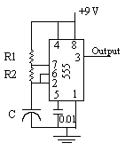
The operational equations are:
T1 = 0.693*(R1 + R2)*C = time the output is high (s)
T2 = 0.693*R2*C = time the output is low (s)
f = 1.44/((R1 + 2*R2)*C) = oscillation frequency
(Hz)
For a 50% duty cycle set R1 small compared to R2 but not 0. If you set R1 to 0 the circuit becomes a one shot multivibrator and does not oscillate. A useful configuration is to make R1 a fixed resistor (say 1K) and R2 a variable resistor (say a 100K pot) then you can adjust the flash rate by adjusting R2. Some typical values of R1, R2, and C to get about a 1 Hz oscillation with a 50% duty cycle are:
| R2 | R1 | C | T1 | T2 | f |
| 22K | 1K | 47uf | 0.75 s | 0.72 s | 1.28 Hz |
| 220K | 1K | 4.7uf | 0.72 s | 0.72 s | 1.38 Hz |
| 100K | 1K | 4.7 uf | 0.33 s | 0.33 s | 3 Hz |
A 555 can supply about 200 mA to the output, which is enough to drive 10 LEDs directly. Simply connect a resistor and LED in series with the output and ground. Choose the resistor in the same manner as before using 5/6 of the drive voltage as the output voltage of the 555. For example, if the 555 is powered with a 9 volt battery, the output "high" voltage is 7.5 volts. A resistor for this circuit would be (7.5 - 2.2)/20e-3 = 265 ohms, so use a 270 ohm or a 220 ohm resistor should work.
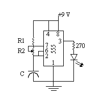
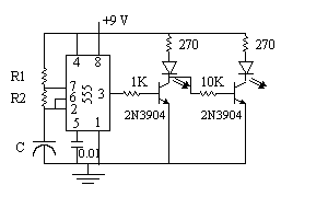
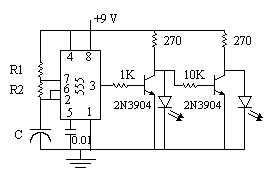
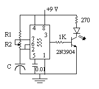
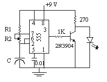
To drive more than a few LEDs or to drive an incandescent bulb you must add a transistor driver to the circuit. The following two circuits both drive a single diode, the left uses the transistor as a switch and the right uses the transistor as an inverting amplifier. In the left circuit, the LED is on whenever the 555 output is high. In the right, the output is inverted and the LED is on when the 555 output is low and off when it is high. The left circuit is useful if you want to make the LED flash, that is have a short on time and a long off time (R2 small and R1 big). Both of these circuits can drive an incandescent light as well as an LED though you must adjust the resistor to supply the correct voltage to the incandescent light. The small, 0.01 uf capacitor on pin 5 of the 555 is for stability. The 2N3904 is a good, general purpose, NPN transistor.
Building the Circuit
When building IC circuits, breadboard them first to check the wiring and component values before soldering them together on some perfboard. or a printed circuit (PC) board. Unless you really know what you are doing, use a socket for the IC so you don't damage it with heat from the soldering iron or with static electricity. A single static spark damages most ICs. CMOS ICs are especially vulnerable. When soldering a transistor, put a heat sink (clamp or forceps) between the transistor and where you are soldering to protect the transistor.
Alternating Flashers
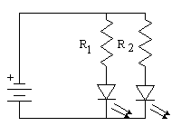
If you want two alternating flashers, such that when one is on the other is off, you can do so with a single 555 and two LEDs or with a 555 and two transistors, one inverting and the other not. The circuit shown below drives two LEDs with the output of the 555. When the output of the 555 is low, current flows through the upper LED turning it on. When the output of the 555 is high, current flows through the lower LED.
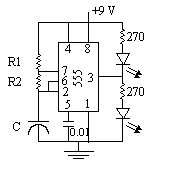
The second circuit is shown in two configurations and uses two transistor drivers, the first inverting the output of the 555 and the second inverting the output of the first. These circuits have the advantage of being able to drive more current than a direct connection to the 555.
LED Chaser
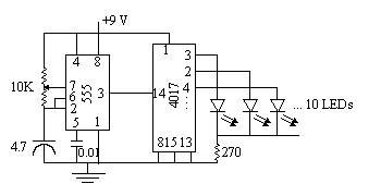
An LED chaser is a line or circle of 10 LEDs with the lit LED running down the line or around in a circle. An LED chaser is created by connecting the output of a 555 to a 4017 decade counter and then placing an LED on each of the 10 outputs of the 4017. The pinout of the 4017 is shown here.
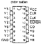
4017 Pinout
As the output of the 555 oscillates, the 4017 counts
those oscillations and sets one of its output pins, Y0 to Y9,
high according to that count. When the 4017 counts to 10, it pulses
the carry output (CO) and starts over with pin Y0. The carry output
would normally be connected to the input of a second 4017 but
that signal is ignored in this circuit. Each output of the 4017
drives up to a 20mA load but no more so you can drive a single
LED on each output. If you need more power you will have to add
a transistor driver to each output. The output of the 555 connects
to the clock pin (CLK), and the inverted enable (CLKEN) and the
clear (CLR) pins must be connected to ground. A good configuration
has C = 4.7 uf and R1 and R2 replaced with a 10K pot with the
wiper on the pot (the center pin) connected to pin 7 on the 555.
I built the whole thing into an Estes Fat Boy nose cone (BT-80
2.6" dia) with the LEDs running around the circumference
of the nose cone. The total weight including the circuit, the
LEDs, the 9 volt battery and the nose cone is 4 oz. (111 gm).
Modified Toys
Another great source for flashing lights are kids toys. The super alien blaster ray guns are the best. They run on 3 volts and have 5 lights that either chase or flash randomly depending on the setting. They also have sound effects (bombs falling, alien spacecraft, explosions, etc) that all seem appropriate for a rocket. I found this one in my son's toy box in pretty bad shape and after convincing him to let me have it I removed the circuit from the plastic case. I removed a motor that makes the gun shake when you fire it (my rockets shake enough as it is). I also exchanged the 3 inch speaker that came with it for a smaller PC board speaker. After stripping off all the plastic, motor and speaker, I was left with a circuit board about 2 inches long and 3/4 inch wide with all the circuits and a full set of transistor drivers as this circuit was designed to drive miniature incandescent lights. I replaced the incandescent lamps with large, high brightness LEDs and stuck the whole thing in a BT-60 nose cone (1.6" dia) which fits on an Estes Big Bertha or on a BT-60 payload section. The circuit runs on two AAA batteries and is turned on by jumpering two wires together. The total weight of the circuit the LEDs, the batteries and the nose cone is 2 oz. (56 gm).
Other useful circuits are the toy telephones that make a different beep depending on what button you press and a candy dispenser that flashes lights and beeps whenever you get a candy out of it. Naturally, the candy dispenser was empty by the time I got to it. In both cases, the circuits run on hearing aid batteries and are very light weight, especially after I cut away the unnecessary parts of the printed circuit board such as that part that was under the keys of the telephone. Go digging in your kid's toy box (make sure they are not around when you do) and see what you can find. Anything that has lights and makes noise is a candidate for rocket lights.
Return to top.
IV. Photoflash Strobe Lights
WARNING; They Bite !!!!!
Let me make one thing clear. Photoflash capacitors bite and bite hard. The photoflash (200 uf) capacitor in an inexpensive camera driven with a single 1.5 volt AA battery gets charged up to about 250 volts and contains 0.05 coulombs of charge. If that charge is dumped into your finger in 1 ms, that works out to 50 amps at 250 volts.!!! That amount of power could kill you if it can get to your heart. Across a finger it hurts a lot. It can also accidentally short to other parts of the circuit, burning them out in a flash. To protect yourself, short the terminals of the capacitor with a shorting strap whenever you are fooling with the circuit. A good shorting strap consists of a short piece of insulated wire with insulated alligator clips on its ends. Note the emphasis on insulated. When you clip the shorting strap onto the capacitor, use only one hand to do so. Your other hand should be in your pocket until the capacitor is discharged. To prevent the big spark and loud noise when you first discharge the capacitor, discharge it with a 100 to 1K ohm resistor for a few seconds first then short it with the strap. Be sure to insulate the resistor before holding it in your fingers to discharge the capacitor.
A Basic Flasher Circuit
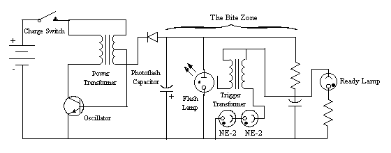
A basic flasher circuit consists of three parts, the high voltage power supply, the xenon flash lamp, and a trigger circuit. The high voltage power supply charges a large capacitor to 150 to 300 volts. The xenon lamp is attached directly to the terminals of the charged capacitor. The trigger circuit delivers a high voltage pulse to a wire or piece of foil sitting next to the xenon flash lamp. When the trigger fires, the charged wire causes the xenon to ionize. When the xenon ionizes, it conducts electricity and shorts the energy in the capacitor through the xenon causing it to flash.
Modifying Disposable Cameras
Small, disposable flash cameras contain a flasher circuit that can easily be modified to make a flasher for a rocket. These cameras are a good source of flashers because they are small and light, operate on low voltage, and are usually available for free from your local photo shop.
To modify a flash from a camera for use as a flasher in a rocket, you must
- remove the flasher circuit from the camera
- make the high voltage supply continuously charge the capacitor
- make them flash repetitively
- increase the flash rate to about once per second
- modify the circuit board so it will fit in a payload section.
Remove the flasher circuit carefully from the camera body. Most of the cameras are of a snap together design so when you snap apart the camera, you will see the circuit board sitting beside the lens on the front of the camera. As soon as you get access to the circuit board, place a shorting clip across the capacitor and remove the battery. You should now be able to lift out the circuit board.
The high voltage power supply found in most cameras consists of a transistor oscillator tied to a transformer. The transformer is coupled to the photoflash capacitor through a diode. The high frequency oscillations through the transformer generates the high voltage in the transformer's secondary winding which is rectified with the diode and charges the photoflash capacitor. Most cameras also have an LED or neon lamp connected in series with the photoflash capacitor and a large resistor to serve as a sensor to tell you when the capacitor is charged. The high voltage power supply is either turned on with a switch that you must hold down until the capacitor is charged or it has a transistor circuit that keeps the power on as long as you are taking pictures. No matter which type of camera you have, both have a switch to start the charging process. Soldering a wire across that switch makes the power supply circuit stay on as long as a battery is connected.
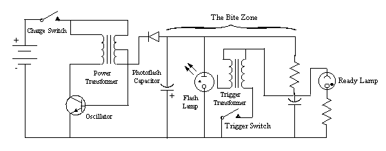
The trigger circuit drains some power from the photoflash capacitor to charge a trigger capacitor. The trigger capacitor is connected to a trigger transformer and a switch. When the switch is closed, the capacitor is discharged through the trigger transformer which then generates a high voltage pulse at its secondary terminals. This high voltage pulse then triggers the flash.
Flash cameras are designed to make a single flash whenever you press the shutter. To make them flash continuously, you need to change the circuit to automatically close the trigger switch whenever the capacitor is charged. I have seen two types of trigger switches, a simple on/off switch and a transistor switch that is activated with an on/off switch (Kodak). Cameras with a single on/off switch are the easiest to modify. What is needed to fire the trigger circuit is a rapid switching of the trigger capacitor so that it discharges through the trigger transformer. The rapid switching is necessary for the transformer to develop sufficient voltage to fire the lamp.
Triggering With Two NE-2s
A simple trigger circuit is to place two, fresh, NE-2 neon lamps in series across the trigger switch. Neon lamps are normally nonconducting until the voltage reaches 70 volts, at which point the neon gas breaks down and becomes highly conducting. The neon lamps sense the voltage at the switch, which is the voltage across the trigger capacitor. When that voltage reaches 140 volts (2 * 70 volts) the neon lamps turn on and discharge the capacitor through the transformer. The neon lamps must be new because after they age a little while, the gas breakdown gets soft and does not turn on the circuit fast enough to make a high enough voltage pulse to fire the xenon lamp.
Triggering With An SCR
Another circuit places a SCR across the trigger switch. The trigger wire of the SCR is then attached to a circuit that senses the charge on the photoflash capacitor. Note that while the SCR can hold off several hundred volts, the trigger terminal needs only about 1 volt to turn on the SCR. The voltage needed to turn on the SCR is measured from the cathode (the top terminal in the figure below) and the trigger (the terminal on the side in the figure below). Anthony Cooper designed a circuit with two diodes in series above the ready lamp. Diodes have about a 1/2 volt drop across them no matter what current is flowing through them. Two diodes have a combined voltage drop of just over a volt, which is enough to trigger the SCR. In the circuit below, the ready lamp is a neon bulb that lights when the capacitor is charged. When the ready lamp is off, no current flows through the diodes so the voltage at the trigger terminal of the SCR is 0. When the neon ready lamp lights, current flows through the resistor causing a voltage on the trigger terminal of the SCR, turning it on and firing the flasher.
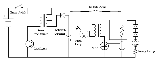
| Note: I have recently done some more work with this circuit, and found that the two diodes are not necessary in all cases. In circuits I have tested, removing the diodes has no effect on the operation of the circuit because the trigger leg of the SCR serves the same purpose as the two diodes. Connecting from ground, through a reisistor, a neon lamp and then directly to the trigger of the SCR works just fine. You may need to adjust the resistor value to get the best results with your particular SCR. |
If your circuit has an LED ready lamp, you will need to measure the voltage difference between a terminal of the trigger transformer and some point in the ready lamp circuit. Find a point that has a voltage difference of a volt or two when the ready lamp is on and zero when it is off. This point is where to connect the trigger terminal of the SCR.
Making It Flash Faster
Most flash cameras when modified in this way will flash about once every 5 seconds. This is much too long of a time between flashes for a rocket. You need about one flash per second to be able to use the flasher to follow a rocket. To speed up the flash rate, reduce the capacitance of the photoflash capacitor. Most photoflash capacitors on small cameras are around 100 to 200 mfd. Replacing that capacitor with one of 10 to 20 mfd makes the flasher run at about one flash per second without significantly reducing the brightness of the flash. You may need to experiment a little to find the capacitance that gives the flash rate you want. Keep in mind that the charge rate of a capacitor and thus the flash rate is proportional to the capacitance.
Making It Fit In A Rocket
The last step is to modify the circuit board to fit
into a rocket's payload section. The camera circuits are modified
to fit in a BT-50 payload section by folding the circuit board
in half. As you might imagine, circuit boards do not fold so you
must cut the board in half and then solder small wires from one
half to the other to reconnect the printed circuit foils that
you cut.
First draw a diagram of the foils on the board or
have a second camera available so you can see where the connections
belong after you cut the board. Cut the circuit board with a fine
toothed saw or score it with a file and snap it. Be careful to
not break one of the components when cutting the board. After
cutting the board in half, I glued the two halves to adjacent
sides of the trigger capacitor with rubber cement. After the cement
dried, I soldered jumpers on the board to reconnect the foils.
Note that you do not have to solder to the foils at the edge where
they are cut but may solder to any convenient point on the foil.
Another option if you have the capability and inclination is to make your own circuit boards. Anthony Cooper has a complete set of plans on this web site
for making the PC board. He unsoldered all the components from his camera, made his own circuit board that would fit into a rocket, and soldered the components on it.
Using the ALL FSH-1 Flasher
(Note: Major revision in this section 4/19/1998)
All Electronics (see section VIII. Sources) sells a surplus flasher unit called the FSH-1 for $3.75. This unit, while not free, is an ideal size for a rocket flasher. The whole unit is only two and a quarter inches long and an inch wide which easily fits in a BT-60 payload section. The unit was apparently manufactured for a better camera than the throw-aways discussed above. It has better electronics and charges faster than the throw-aways. The circuit is more complicated than the throw-away cameras but operates in much the same way. It has a circuit to hold on the charging circuit so you don't have to hold a switch down to charge the camera and has a transistor switch to trigger the flash. The circuit operates on 3 volts.
The first thing to note when trying to use this camera is that the wiring diagram that comes with the camera is wrong. It sort of works, but incorrectly marks the terminals. The circuit board has three terminals as shown below. A momentry grounding of terminal A turns on the charging circuit. This circuit stays on for several minutes and gets reset if you flash the camera. Terminal B is for connecting the charge indicator and connecting terminal C to the positive side of the battery triggers the flash.
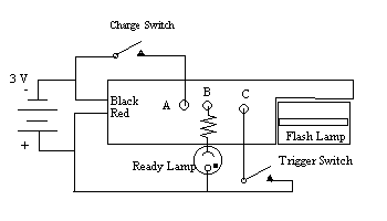
The second thing to note is that the capacitor is charged to a positive high voltage with respect to the battery instead of negatively as with the throw-away cameras.
Be careful when working with this circuit because the high voltage traces are right next to the low voltage traces. Don't try to probe the circuit with a volt meter while the circuit is energized because you will blow it up. I have a whole sack full of blown circuits to prove it. A standard probe is large enough to short from the high voltage trace to a low voltage one and dumping the high voltage into the low voltage circuit does bad things to the low voltage circuit. I have had the transistors split in half after such a short. If you want to probe the energized circuit, solder a wire on the connection you want to measure, energize the circuit, and then touch your probe to the wire.
To turn this flasher into a strobe, first replace the 120 mfd photoflash capacitor with a 10 or 20 mfd one to reduct the charging time. Next put a large resistor between terminal A and ground to hold the charging oscillator on. If you short this connection, it drains the battery too fast. I used a 22K ohm resistor but anything between 10K and 100K ohms would probably work. To trigger the circuit, you could use the ready light terminal but the terminal is attached to the photoflash capacitor and does not charge as fast as the trigger capacitor. To make the camera trigger faster, connect a 3M ohm resistor from the top of the trigger transistor (point D in the diagram below which is a solder point imediately to the right of terminal C on the circuit board) to the trigger terminal (C). The resistor was experimentally sized to tap enough current to trigger the SCR when the trigger capacitor is charged but not enough to prevent the trigger capacitor from charging.
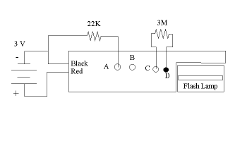
| Note: The FSH-1 can also be triggered by the output of a 555 timer or by one of the outputs of a 4017 counter making it possible to control when the flasher fires. |
Return to top.
V. Attaching The Lights
Now that you have some fancy lights, how do you attach
them to your rocket? Anyway that works, that's how. LEDs can be
attached to a nose cone by first trimming the leads, soldering
wires on them, and then drilling a hole in the nose cone that
is slightly smaller than the LED. Feed the wires through the hole
and glue the LED in place with silicon rubber. The rubber holds
the LED in place and insulates the connections but is removable
if you change your mind or want to move the circuit to another
nose cone. When the glue is dry, you can solder the wires to your
circuit board.
To make your rocket look good, you should try to run the wires inside of the rocket. This is fine in the nose cone or in a payload section but can be a problem in the rocket body. Make sure that any wires in the rocket body will not snag the parachute during ejection. I lost a Big Bertha because I put the circuit board in the rocket body with the parachute. I had the circuit well covered and glued to the inside of the body and the rocket had already flown twice at night. This time the parachute snagged on the circuit board, causing the rocket to make a ballistic landing in the street. The Space Camp Kids gave it a good cheer but I had to replace everything from the fins forward. The circuit board survived; they design those super alien blasters to survive kids so a little rocket splat on the street isn't going to hurt it.
Glue It To The Outside
If you must run wires on the outside of your rocket,
use fine wires and glue them down to the outside of the rocket.
After the glue dries, put a fillet of glue along the wire to make
it appear to be a part of the skin of the rocket instead of a
wire hanging on the outside. Another option for wires on the outside
of a rocket is to use metal foils. Brass foil can be glued to
the outside of a rocket and painted which nearly completely hides
it. Aluminum foil does not work well because you can not solder
to it.
In a pinch, I glued one whole circuit board to the fin of a rocket with hot glue. It looked fine in the dark and was easy to remove later.
Adding A Payload Section And Nose Cone
A good way to attach circuits and lights is to buy
a clear BT-60 payload section and build the circuits into it.
A payload section can be easily moved from one rocket body to
another allowing you to fly several rockets with one set of lights.
An Estes BT-60 payload section comes with a BT-60 and a BT-55
adapter so you can use the one payload section with two different
sized body tubes.
Large nose cones are also good place for circuits and lights. A 5 LED flasher with circuit board and two AAA batteries fits in a BT-60 nose cone which fits on many of the larger rockets. If you buy an extra nose cone for a rocket, you can fly it in the daylight with the normal nose cone and switch it for the lighted one at night. A nose cone can also be moved from rocket to rocket as long as they have the same diameter body tube.
Return to top.
VI. Batteries
Choosing the correct batteries for a lighted rocket
is an important task as batteries are large and heavy. You need
to have the smallest, lightest battery you can find that has the
correct voltage, can provide sufficient current, and that has
sufficient capacity for your circuit. The following table shows
the sizes and capacities for several of the more common batteries
that are good candidates for rocket lights.
| Battery, Designation | Voltage | Capacity | Weight | Size |
| 357 (silver oxide)
D303, SR44 | 1.55 V | 165 mah into 1K ohm (1.5 mA) | 2.3 gm | 11.5 mm dia. x 5.6 mm |
| AAA (alkaline) LR03 | 1.5 V | 1150 mah into 75 ohm (15 mA) | 11 gm | 10.5 mm dia. x 44.5 mm including tip |
| AA (alkaline) LR-6 |
1.5 V | 2850 mah into 43 ohm (25 mA) | 23.6 gm | 14.5 mm dia. x 50.5 mm including tip |
| C (alkaline) LR-14 | 1.5 V | 7800 mah into 20 ohm (60 mA) | 65 gm | 26.6 mm dia. x 50 mm including tip |
| 9V (alkaline) 6LR61 |
9V | 580 mah into 620 ohm (14 mA) | 45.9 gm | 17.5 mm x 26.5 mm x 48.5 mm including snap |
| 9V Sub cells | 1.5 V | 580 mah into 100 ohm (14 mA) | 7.5 gm | 8 mm dia. x 43 mm, tear apart a 9V cell |
Button Cells
The smallest batteries generally available are button
cells (hearing aid and watch batteries.) A good choice is the
357 silver oxide battery, which has a voltage of 1.55 V and a
capacity of 165 mah (milliamp-hours) rated at 1.5 mA into a 1K
ohm resistor. The current capacity might seem a little low for
driving a 20 mA LED, but they work just fine. I have driven four
LEDs using two of these cells in series. A unique characteristic
of this cell is that two of them fit in the nose cone of an Estes
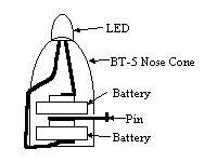
Mosquito (a BT-5 nose cone).
Lithium cells which operate at 3V might seem to be a better match for LEDs which need about 2 volts to turn on. But, lithium cells can not sustain a drain of more than a few mA which can not drive an LED..
Flashlight Batteries
Flashlight batteries come in several sizes from AAA through D and all operate at 1.5 volts. Most rockets will not be able to lift a couple of D cells and it is unlikely that a rocket lighting application will need that much power. An AAA cell is much smaller, lighter, and has a capacity of 1150 mah which is more than enough for most applications. If you need a smaller 1.5 volt cell, see the 9V sub cells described in the next section.
9V Transistor Radio Battery
Transistor radio batteries are useful for the flasher
circuits because they supply a voltage that fits well with the
requirements of integrated circuits. They are also relatively
light and have a capacity of 580 mah. In addition, the 9V battery
snap makes a good, inexpensive switch.
A single 9V rectangular cell actually consists of 6 small cylindrical sub cells in series. Each of the sub cells operates att 1.5 volts. If you need some smaller cells at less than 9V you can carefully disassemble the 9V and remove and use the sub cells where you would use a flashlight battery.
Lifetime
A big question is how long will a battery last in
a given situation. You don't want the battery to go dead while
the rocket is sitting on the pad waiting for its turn to launch.
This is especially true if you have soldered in the batteries.
A battery's capacity is given in milliamp hours (mah) into some
standard load. One milliamp hour is a duration of one hour with
a current draw of one milliamp or two hours with a current draw
of 1/2 milliamp and so forth. The standard load is sized to the
battery's chemistry to optimize the current and the capacity.
If you use a lower resistance load (higher current) the capacity
will be reduced because the battery's chemistry can not keep up
with the higher current draw. Higher resistance loads are no problem.
To calculate how long a battery can power a given circuit divide the battery's capacity by the current drain in the circuit. For example, two 357 button cells in series can directly drive a single LED with about a 20 mA current drain: (165 mah)/20 mA = 8.25 hours (sort of). This calculation is not exactly right, as the capacity was determined with a standard load that gave a current draw of 1.5 mA. The LED is draining the battery at more than ten times the rated drain. The higher drain rate should reduce the capacity. If the cell is run at the higher drain rate for short periods of time and then turned off, the total capacity of the cell will approach the rated capacity. As another example, consider a 1.5 V AAA battery driving a 100 mA incandescent bulb: (1150 mah)/100 mA = 11 hours.
Soldering To Batteries
Battery manufacturers do not recommend soldering
to batteries because the heat needed to solder to the batteries
can damage the cells. However, soldering to the batteries saves
the weight of a battery holder, which can be significant. When
soldering to a battery, you need to do everything possible to
prevent the battery from overheating. If a battery starts getting
hot while you are soldering it, stop, and let it cool off before
trying again.
To solder a wire to a battery, first clean with emery
paper the metal where you are going to solder. Tin the spot you
have just cleaned by applying your soldering iron and solder.
As soon as the solder flows on the surface of the battery, remove
the iron and let the battery cool. Tin the wire you are going
to solder to the battery. Hold the tinned wire against the tinned
spot on the battery and apply the soldering iron to the tinned
wire, pressing it down against the battery. In this way, the wire
is heated first and then the battery, reducing the time the battery
is heated. As soon as the solder on the battery melts, remove
the soldering iron from the battery and let the battery cool.
I have soldered wires to all the batteries in the table above, including the button cells, without doing any apparent damage to the batteries.
Return to top.
VII. Switches
You have a circuit, lights, and batteries; now all you need is a way to turn them on. The simplest switch is to twist the wires together. Twisted wires works fine but a nice switch looks a lot better and is more reliable.
Miniature Toggle Switches
Miniature toggle switches can be purchased at your
local electronics store. A toggle switch gives a good professional
look to a project, especially when compared to two wires twisted
together. Be careful when ordering the switches, as there are
many different sizes, some of which are quite heavy. I picked
up some miniature toggle switches from All Electronics which weigh
only 0.1 ounces (3 gm) and cost $1.35.
Another thing to worry about with toggle switches is accidentally turning them off by bumping the switch.
Closed Circuit Phone Jacks
Miniature (2.5 mm), closed circuit, phone jacks make good switchs that are largely hidden when they are turned on. These jacks have an internal switch that opens when the phone plug is inserted. Wire the jack so that the power is turned on when the plug is removed and off when it is inserted. Attach a flag to the plug so you don't forget to pull it before launch. The miniature jacks weigh only 0.04 ounces (1 gm).
Finger Strips
Finger strips are RF shielding strips you see around the edge of removable panels in good quality electronics boxes. The strips consist of many spring loaded fingers on a long metallic strip. They are attached around an opening in an electronic box so that when you close the opening the fingers make good electrical contact with the door. Normally, they come in rolls or long strips, but may be hard to find. If you can find an old electronics box at a swap or salvage sale, you can remove them from the box.
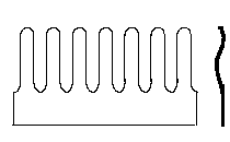
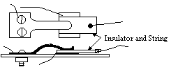
To make a switch, cut one finger from a strip and drill holes in the mounting side. Attach to an insulator (the side of your rocket) and mount another metal strip under the spring loaded finger. Connect one wire to the finger and one to the strip. When the metal finger touches the metal strip the switch is on. To turn it off, attach a string to a small paper or plastic insulator and slip the insulator under the spring loaded finger. To turn it back on, simply pull out the insulator. This switch can be set to turn on when at the moment of launch by tying the string to the pad. At launch the string pulls out the insulator and turns on the switch. This could also be set to turn on when the ejection charge fires as it takes only a little force to pull out the paper.
Wire Short Between Two Batteries
When putting lights on an Estes Mosquito, I needed
an extremely light weight switch so as to not load down the tiny
rocket. A second problem was that the two button cell batteries
that were pressed into the nose cone tended to separate after
experiencing a little vibration, breaking the circuit. I didn't
want to put a spring in the nose cone to hold the batteries together
because of the added weight (I wasn't sure how I was going to
get it in there anyway.)
This solution solved both problems. Each battery has one wire soldered to it. These two batteries are held together and pressed into the nose cone and glued in place. At the point on the outside of the nose cone where the two batteries come together I drilled a small hole and pressed a small wire or pin into the hole between the batteries separating them slightly. When the pin is removed, the batteries do not touch and the circuit is open. Press the pin in and it contacts the two batteries completing the circuit. There you have it, a switch with the weight of a pin.
PC Board Connectors And Jumpers
The small connectors for attaching wires to a pc board make a good switch. The small female connectors have a wire connected to a spring loaded clip in a small plastic housing. Normally, these connectors are pressed onto a pin on a pc board however they make a good connector for connecting two wires together. Solder one wire to the connector and then press the second wire into the hole on the connector when you want to make a connection. Another useful clip is an option jumper. These are the small clips pressed onto two pins on a disk drive to short the two pins together. To use them as a switch, solder one wire to the jumper and insert the other into either of the two holes on the jumper to make the connection.
9V Battery Snap
Circuits with 9V batteries come with a built-in switch. Simply snap the battery onto the battery connector to turn a circuit on and snap it out to turn the circuit off. To work with the circuit, snap only one side of the battery onto the connector so that it can rotate. Rotate the connector on the end of the battery until the second snaps touch turning the circuit on. Rotate them apart and the circuit turns off.
Return to top.
VIII. Sources
Some sources for LEDs and other interesting parts and things.
All Electronics, 800-826-5432, http://www.allcorp.com, Surplus electronics, lots of LEDs, some components.
Jameco Electronics, 800-831-4242, http://www.jameco.com, Lots of electronics and components.
Radio Shack, all over, a few LEDs and a small selection of components.
Target has a lighted key ring for about $2.50 that contains two 357 batteries and a red LED for less than you would pay for the two batteries.
National Electronics, http://www.national.com/design/, IC data sheets available online.
Texas Instruments, http://www.ti.com, IC data sheets available online.
Don's Xenon Flash and Strobe Page, http://www.misty.com/~don/donflash.html, Lots of flasher circuits.
Anthony M. Cooper's Strobe circuits, http://www.dsp.net/dmmill2/Flasher.html, Modified cameras. Anthony has a working flasher circuit made from a disposable camera including pictures and all the artwork for a printed circuit board available on this web site.
Duracell technical data web site, http://www.duracellnpt.com, Lots of information about batteries, size weights, capacity, etc.
Copyright © 1998 by LUNAR, All rights reserved.
Information date: March 31, 1998 wjo
